

 English
  русский
 Content
- 1 Casting Ball Mill Liner: Geometry, Metallurgy and Wear Life in High-Tonnage Grinding Circuits
- 1.1 What are mill liners? A functional definition for grinding circuit engineers
- 1.2 Shell liner geometry: the parameters that actually matter
- 1.3 What are the different types of liners used in ball mills? Profile families and their applications
- 1.4 End liners, trunnion liners and the discharge end
- 1.5 What are ball mill liners made of? Alloy families and their behaviour
- 1.6 Wear progression: how a Casting Ball Mill Liner actually fails
- 1.7 Liner profile and mill power draw
- 1.8 Fastening systems for Casting Ball Mill Liner assemblies
- 1.9 Casting process control for Casting Ball Mill Liner production
- 1.10 Dimensional tolerances that determine whether a liner set fits
- 1.11 Installation practice and torque control
- 1.12 Wear monitoring: building a measurement routine
- 1.13 Reading wear patterns to diagnose circuit problems
- 1.14 Specifying a Casting Ball Mill Liner set: what the foundry needs from the plant
- 1.15 Common questions answered with engineering detail
- 1.16 Selection matrix by compartment and duty
Casting Ball Mill Liner: Geometry, Metallurgy and Wear Life in High-Tonnage Grinding Circuits
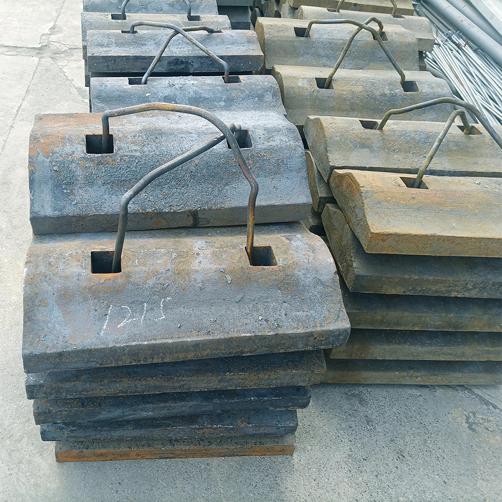
A grinding circuit is only as stable as the wear parts inside its shell. The Casting Ball Mill Liner is not a passive plate bolted to a cylinder. It is a process variable that sets the height of the ball charge, the angle at which grinding media release, the power drawn by the drive, the noise level of the mill, and the size distribution of the product leaving the discharge trunnion. Engineers who treat the liner as a consumable purchased on price alone frequently discover that the cost per ton of finished powder rises rather than falls.
This reference page collects practical engineering data on how Casting Ball Mill Liner geometry is defined, how alloy selection interacts with abrasion and impact, how wear is measured and predicted, and how a foundry converts a mill survey into a repeatable casting. It is written for plant metallurgists, maintenance planners, grinding circuit supervisors, and project engineers who need numbers rather than slogans.
What are mill liners? A functional definition for grinding circuit engineers
What are mill liners? In the narrowest sense, a mill liner is a replaceable wear plate that shields the mill shell, end walls, and trunnion faces from direct contact with grinding media and ore. In the broader engineering sense, a mill liner is the interface that converts rotary motion of the shell into useful work inside the grinding chamber. Without a liner profile, a rotating cylinder would simply drag its ball charge around the shell in a slipping mass. The lifters cast into the liner raise the charge to a defined release angle, and the subsequent free fall delivers the impact energy that fractures coarse particles.
Every liner decision therefore carries two consequences. The first is wear life: how many operating hours the plate survives before its profile collapses. The second is grinding performance: how the charge trajectory changes as the lifter wears down. A liner that lasts twice as long but loses its face angle in the first quarter of its life may deliver a worse overall result than a shorter-lived plate that holds its geometry. This dual role is why liner specification belongs in the grinding circuit mass balance, alongside ball charge, pulp density, and mill speed.
Liner profile determines the effective internal diameter of the mill, the total charge volume, the height of the cataracting zone, the slip between charge and shell, and the residence time of pulp in each compartment. Changing a liner alloy without changing the profile changes wear life only. Changing the profile without changing the alloy changes the grinding curve. Changing both at once changes the entire circuit balance and requires a fresh survey.
Shell liner geometry: the parameters that actually matter
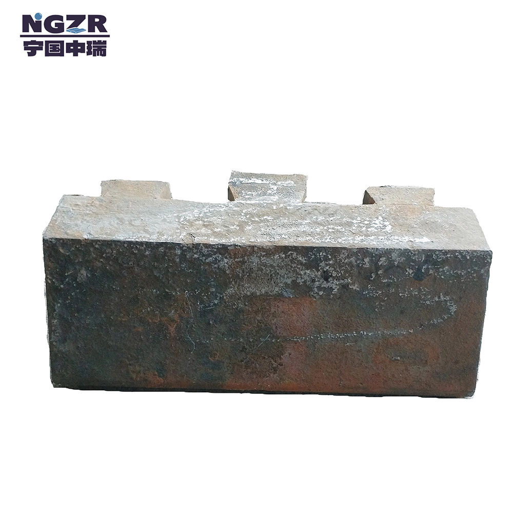
A Casting Ball Mill Liner fitted to the cylindrical shell is described by a small set of geometric parameters. Each one has a measurable effect on charge motion and on wear rate. When a mill survey is carried out, these are the dimensions that should be recorded for every row of plates.
The radial distance from the shell surface to the highest point of the lifter face. Typically 40–120 mm in a primary ball mill, and 25–70 mm in a regrind or secondary mill. Higher lifters increase impact energy and mill power draw, but also increase the risk of ball breakage and liner cracking in the root fillet.
The angle between the leading face of the lifter and a radial line. A face angle between 0° and 25° produces a steeper release and a more cataracting charge. A negative or undercut face angle holds the charge longer and promotes a cascading, abrasion-dominated motion.
The circumferential centre-to-centre distance between adjacent lifters. Pitch controls how many times per revolution the charge is lifted and released. Narrow pitch gives more frequent but smaller lifts; wide pitch gives fewer, higher-energy releases.
Usually quoted as a nominal value plus a wear allowance, for example 50 mm + 45 mm. The wear allowance is the sacrificial metal above the minimum structural thickness required to keep the bolt heads and the plate root sound.
The internal diameter measured across the tips of the lifters. This dimension, not the shell bore, governs the critical speed calculation and the actual power draw of the drive.
The fillet where the lifter meets the backing plate. Sharp roots concentrate stress and are the origin of most fatigue cracks in large Casting Ball Mill Liner castings. A generous radius of 8–15 mm is standard practice.
These parameters interact. Increasing lifter height without widening the root radius raises the stress at the base. Narrowing the pitch without reducing the height increases the number of low-energy impacts and accelerates abrasion on the plate face. A foundry that receives only a thickness and a bolt pattern is receiving an incomplete specification, and the resulting liner may fit the mill perfectly while performing poorly.
What are the different types of liners used in ball mills? Profile families and their applications
What are the different types of liners used in ball mills? The answer is usually organised by profile family, because profile is what the operator sees and measures. The families below cover the majority of industrial installations. Each profile is a compromise between lifting capability, wear distribution, and the type of breakage the circuit needs.
A low-profile plate with minimal lift. Used in fine grinding compartments where impact is not required and surface abrasion dominates. The low lift keeps the ball charge in a cascading state, maximising attrition between balls and promoting a narrow product size distribution.
A sinusoidal cross-section that lifts the charge moderately and distributes wear across a broad face. The rounded crest reduces peak contact stress and lowers the risk of ball breakage. Common in the first compartment of cement mills and in coarse grinding circuits where the feed top size is moderate.
A rectangular or trapezoidal lifter with a flat leading face and a flat wear plate between lifters. The sharp edge provides strong lift and a defined release point, which is desirable in primary grinding where large rocks must be broken by impact. Wear tends to concentrate on the leading face, and the profile degrades from a step into a wave over its service life.
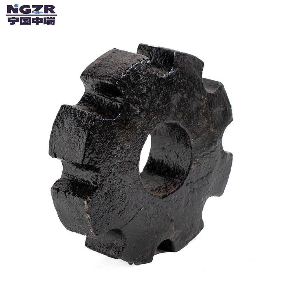
Two lifters cast into a single plate, giving a higher lifter count per shell circumference without reducing plate width. The result is a more frequent, more controlled release and a smoother power draw curve. Often specified for large diameter mills where shell distortion makes very wide plates difficult to seat.
A plate with an overlapping lip that protects the joint between adjacent plates from pulp erosion. The overlap also stiffens the assembly against shell deflection. Used in wet grinding circuits where the pulp is abrasive and the joints are a known failure point.
Not a casting, but a competing solution that must be evaluated alongside it. Rubber liners are moulded rather than cast, so lifter geometry is limited by moulding practice. They perform well in secondary and regrind mills with small media and low impact, and poorly in primary mills with large balls and high drop heights.
The selection between these families is driven by feed top size, ball diameter, mill speed as a percentage of critical speed, pulp density, and the target grind size. A circuit aiming for a coarse liberation size with a high tonnage throughput will usually favour a step profile. A circuit aiming for a fine product with a controlled size distribution will usually favour a wave or flat profile. Mixed profiles within a single mill—stepped lifters in compartment one, smooth plates in compartment two—are normal practice in multi-chamber installations.
End liners, trunnion liners and the discharge end
Shell liners attract most of the attention, but the end walls of a mill experience a different wear regime. At the feed end, the liner faces the incoming ore stream and the tumbling edge of the ball charge. At the discharge end, the liner faces the outflow of pulp and the sliding of the charge against a stationary surface. Casting Ball Mill Liner components for the ends are usually manufactured from the same alloy family as the shell plates, but with different section thicknesses and a different fastening arrangement.
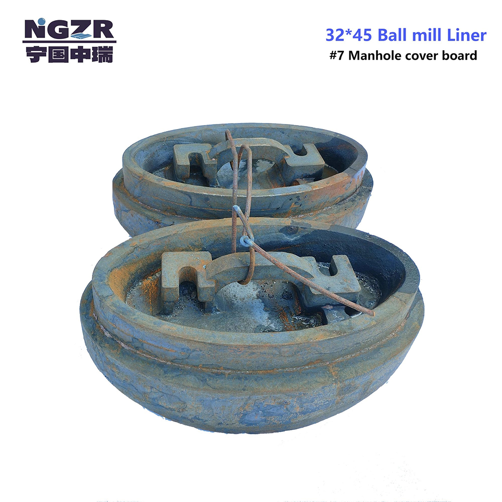
Often a segmented ring of plates with radial ribs. The ribs guide the incoming feed toward the charge and prevent the formation of a dead zone at the trunnion. Thickness is normally greater than shell plate thickness because the feed end absorbs the direct impact of the dropping charge. A common failure mode is erosion at the feed chute opening, where high-velocity ore strikes the plate at an oblique angle.
A conical or cylindrical casting that protects the hollow shaft bore from sliding abrasion. Because pulp velocity is highest here, these parts are frequently cast in a higher-chromium grade or fitted with a replaceable wear sleeve. Ovality of the trunnion liner is critical: an out-of-round bore disturbs the pulp flow and accelerates wear on one side.
The discharge end combines a structural plate with an aperture pattern that controls the exit of pulp. It must resist abrasion from the moving charge and erosion from the outflowing slurry. Plates are usually thicker near the centre, where the charge velocity relative to the plate is highest.
In grate discharge mills, the discharge end carries a grate plate with slots or holes, behind which sit pulp lifters. The grate sets the maximum particle size that can leave the mill. The pulp lifters raise the slurry to the discharge trunnion. Slot width, slot taper, and open area are all specified together, because a grate that is too open passes coarse material while a grate that is too tight causes pulp to pool and the mill to choke.
What are ball mill liners made of? Alloy families and their behaviour
What are ball mill liners made of? The answer depends on which wear mechanism dominates at the liner surface. Abrasion, impact, corrosion, and heat each favour a different microstructure. A single mill may experience all four mechanisms at different points, which is why mixed-alloy installations are common.
| Alloy family | Typical hardness | Impact resistance | Abrasion resistance | Corrosion resistance | Preferred duty |
|---|---|---|---|---|---|
| Austenitic manganese steel | HB 180–220 as cast; HRC 45+ after work hardening | Very high | Moderate | Moderate | Primary grinding, large ball charges, high drop height |
| High chromium white iron | HRC 58–65 | Low to moderate | Very high | High | Secondary and fine grinding, cement, coal, wet abrasive slurry |
| Chromium-molybdenum alloy steel | HRC 45–55 | High | High | Moderate | Mixed duty, large diameter mills, grate plates |
| Nickel hard iron | HRC 50–58 | Moderate | High | Moderate | Medium impact with abrasive ore |
| Bimetallic composite casting | HRC 58–64 at wear face | Moderate to high | Very high | High | Large plates needing a tough backing with a hard face |
| Ceramic-inserted iron | HRA 85–92 at inserts | Low | Extremely high | High | Fine grinding where media are small and impact is minimal |
Austenitic manganese steel remains the default choice for the first compartment of a primary mill. Its surface hardness rises under repeated impact, so the working face becomes harder than the as-cast core while the bulk of the section stays tough enough to absorb a dropped ball without fracturing. The trade-off is that manganese steel resists sliding abrasion poorly compared with high chromium iron, and it performs badly in low-impact, high-abrasion duties where the surface never work hardens.
High chromium white iron delivers the best abrasion resistance per unit of weight among the cast alloys, but its low fracture toughness limits the ball size and drop height it can tolerate. In practice, a high chromium liner is rarely specified for a primary mill with a 100 mm top-size ball charge. It is specified for regrind mills, fine grinding compartments, coal mills, and wet circuits where the dominant loss mechanism is scratching rather than spalling.
Chromium-molybdenum alloy steel occupies the middle ground. It can be heat treated to a range of hardness and toughness combinations, which makes it suitable for grate plates, pulp lifters, and end liners where the geometry is complex and the stress state is not uniform. It is also the usual choice for very large plates, where the thermal gradients during quenching of a high chromium casting would risk cracking.
Carbide volume fraction, carbide morphology, and matrix hardness together determine abrasion resistance in white irons. A fine, evenly distributed eutectic carbide network resists scratching better than coarse, continuous carbide blades that can be undercut and pulled out. In manganese steel, grain size and the completeness of the solution treatment control the work-hardening response. An under-solutioned casting will harden unevenly and may crack at the surface before the bulk has absorbed any energy.
Wear progression: how a Casting Ball Mill Liner actually fails
Liner wear is not linear. In most installations the first few hundred hours produce rapid dimensional change as the sharp edges of a new casting are rounded off, after which the wear rate settles into a slower, steadier phase. The final phase begins when the lifter height falls below the level needed to lift the charge effectively; at that point the charge begins to slip, the wear pattern changes, and the remaining thickness can be lost faster than the earlier trend would suggest.
Curves are indicative and are intended to illustrate shape rather than absolute life. Actual values depend on ore hardness, ball size, pulp density, mill speed, and alloy quality.
The practical implication is that liner life should be tracked as a curve, not as a single number. A plant that records thickness at four or five circumferential positions every 1 000 hours will see the curvature develop and can predict the change-out date with reasonable confidence. A plant that measures only once, at the end of life, learns nothing that can be reused.
Liner profile and mill power draw
Mill power draw responds to liner geometry because the lifter height changes the effective diameter of the charge and the height to which the charge is raised. As lifters wear, power draw typically falls. In a circuit operating near the drive limit, this fall can be mistaken for a change in ore hardness. In a circuit operating well below the drive limit, the fall in power is accompanied by a fall in throughput.
Relative power draw at constant mill speed and constant ball charge, expressed as a percentage of the value recorded with a new, full-height lifter. Values are indicative for a typical overflow ball mill.
Two operational conclusions follow. First, if a plant wishes to maintain a constant power draw across the life of a liner set, it must either raise mill speed as the lifters wear or accept a gradual reduction in grinding intensity. Second, if a plant is already at its drive limit with new liners, it has no headroom to compensate for wear, and the throughput decline at end of life will be steeper than the power curve alone suggests.
Fastening systems for Casting Ball Mill Liner assemblies
How a liner is held to the shell is as important as how it is shaped. A liner that fits well but loosens after two weeks will leak pulp, erode the shell, and fail long before its wear allowance is consumed.
The most common arrangement. The bolt passes through the plate and the shell, with a countersunk head sitting flush or slightly proud of the wear face. The head must be recessed deeply enough that it is not worn away before the plate is due for replacement. Bolt grade, thread pitch, and the use of spherical washers all affect how well the joint holds torque under vibration.
The plate is held by a wedge driven into a slot formed between adjacent plates, with the wedge itself retained by a single bolt. This arrangement reduces the number of penetrations through the shell, which lowers the risk of leakage and simplifies plate removal. It requires tighter dimensional control of the plate edges, because the wedge relies on the gap between neighbouring castings.
Permanent magnets embedded in the backing hold the plate against the shell without any penetration. A layer of magnetic ore builds up on the wear face and acts as a sacrificial surface. Suitable for secondary grinding with small media and for installations where shell drilling is not permitted. Not suitable for high-impact primary duty.
Adjacent plates interlock through a tongue-and-groove arrangement, with only a few retaining bolts per row. The interlock carries the circumferential load and reduces the number of bolts exposed to wear. Assembly and removal require a defined sequence, and the first and last plate in each row must be handled specially.
Casting process control for Casting Ball Mill Liner production
The difference between a liner that reaches its predicted life and one that fails early is usually established long before the first heat of metal is poured. Pattern equipment, gating design, moulding sand quality, pouring temperature, and heat treatment all contribute to the final result. A foundry that treats a mill liner as a simple block of alloy will produce a simple block of alloy, and the grinding circuit will pay for it.
The pattern is checked against the mill survey drawing, including lifter height, pitch, face angle, bolt hole position, countersink depth, and the shrinkage allowance appropriate to the alloy. Bolt holes are positioned from a common datum rather than from each edge, so that cumulative tolerance does not cause misalignment on the shell.
Liquid metal must reach the thickest section of the casting before it reaches the thin sections, and must remain liquid long enough for the riser to feed shrinkage. A poorly fed lifter root will contain internal porosity that is invisible from the outside and becomes the initiation point for a fatigue crack under service load.
Carbon, manganese, chromium, molybdenum, nickel, silicon, sulphur, and phosphorus are held within specified ranges. Sulphur and phosphorus are kept low because they segregate to grain boundaries and reduce toughness. Spectrographic analysis is performed on every heat, and the result is recorded against the casting serial number.
Pouring temperature is controlled within a narrow band. Too hot and the grain structure coarsens, reducing toughness. Too cold and the metal freezes before the mould fills, producing cold shuts and misruns. Moulds are poured in a defined sequence and the cooling time before shakeout is specified per alloy.
Manganese steel is solution treated at high temperature and quenched to retain the austenitic structure. White iron is hardened and tempered to develop the carbide-matrix combination required for abrasion resistance. Alloy steel is quenched and tempered to a specified hardness range. Furnace charts are retained as part of the quality record.
Gates and risers are removed, the casting is ground, and critical dimensions are verified. Hardness is checked at defined locations on the wear face. Bolt holes are gauged. Each plate is marked with its heat number, alloy grade, and position in the mill, so that a single plate can be traced from the furnace to the installation.
Dimensional tolerances that determine whether a liner set fits
A liner set that is dimensionally inconsistent will not seat properly. Gaps between plates allow pulp to penetrate, erode the shell, and wash out the backing material. Overlapping plates cannot be bolted down without forcing, which pre-loads the casting and encourages cracking. The tolerances below represent good foundry practice for large shell plates.
| Feature | Typical tolerance | Consequence if exceeded |
|---|---|---|
| Overall length and width | ±3 mm | Gaps or interference between adjacent plates; difficulty seating the final plate in a row |
| Plate thickness | +5 mm / −2 mm | Uneven wear allowance; unpredictable life; balance issues in large mills |
| Lifter height | ±2 mm | Uneven charge lift around the circumference; localised hot spots and accelerated wear |
| Bolt hole diameter | +1 mm / −0 mm | Difficulty inserting bolts; enlarged holes promote movement and bolt fatigue |
| Bolt hole pitch | ±2 mm | Cumulative mismatch along the shell; bolts cannot be entered |
| Countersink depth | ±1 mm | Bolt head protrudes and wears away, or sits too deep and loses preload |
| Back face flatness | 1.5 mm over 500 mm | Point contact against the shell; flexing under load; cracking at the contact zone |
| Face angle | ±2° | Change in charge trajectory; deviation from the designed power draw |
Installation practice and torque control
Correct installation extends liner life by a margin that is often underestimated. The objective is to achieve a uniform, well-supported contact between the casting back face and the shell, with every bolt carrying its share of the load. A single loose bolt allows the plate to move, and movement under a ball charge destroys the plate and the shell in a short time.
The shell surface is cleaned of old backing material, rust, and pulp residue. Bolt holes are inspected for thread damage and re-tapped if necessary. Plates are dry-fitted in sequence before any sealant is applied, so that interference is discovered before the mill is closed up.
A compressible gasket or a bead of sealing compound is applied around each bolt hole and along the plate joints. The seal must tolerate the temperature and pH of the pulp. Over-application of a rigid sealant can prevent the plate from seating and create a false torque reading.
Bolts are tightened in a crossing pattern, in at least two stages: an initial snug pass at roughly half the final torque, followed by a final pass at full torque. Single-pass tightening of a large plate distorts the casting and leaves the first bolts loose after the later ones are drawn down.
After the first 24 to 72 hours of operation, all bolts are re-checked and re-torqued. A second check follows at the first scheduled shutdown. Plates that require repeated re-torquing are usually suffering from a seating problem rather than a bolt problem.
| Bolt size | Typical grade | Indicative final torque | Notes |
|---|---|---|---|
| M20 | 8.8 | 400–450 N·m | Light plates, small mills |
| M24 | 8.8 | 700–800 N·m | Standard shell plates, medium mills |
| M30 | 8.8 | 1 400–1 600 N·m | Heavy plates, large diameter mills |
| M36 | 8.8 | 2 400–2 700 N·m | Primary mills, high impact duty |
Torque values are indicative and must be confirmed against the bolt manufacturer's data, the lubrication used on the thread, and the mill builder's specification for the specific installation.
Wear monitoring: building a measurement routine
A structured wear monitoring routine turns liner replacement from a reactive event into a planned one. The routine does not require sophisticated instrumentation. It requires consistency: the same positions, the same tool, the same interval, and a record that survives personnel changes.
The single most useful derived metric is cost per tonne of liner consumed per tonne of ore ground. It normalises away mill size, ore hardness, and campaign length, and it makes comparison between two Casting Ball Mill Liner options meaningful even when their purchase prices differ substantially.
Reading wear patterns to diagnose circuit problems
The pattern left on a worn liner is a record of what happened inside the mill. Learning to read it shortens the diagnosis of grinding problems that otherwise appear as unexplained changes in throughput or product size.
Indicates a high degree of slippage between the charge and the plate, usually caused by insufficient lifter height, excessive mill speed, or a ball charge that is too small to be lifted effectively. The result is a cascading charge with low impact energy and high attrition. Throughput falls while power draw remains high.
Suggests that the charge is dropping directly onto the base of the lifter rather than onto the toe of the charge. This can be caused by excessive lifter height, mill speed above the design value, or a ball charge that is too coarse. It is an early warning of plate cracking.
Usually points to an out-of-round shell, a misaligned drive, or a persistent dead zone caused by a feed chute that deposits ore on one side. It can also indicate that the plate back faces are not seating uniformly, allowing individual plates to move.
Indicates that the pulp is more aggressive than the alloy was specified for. Raising chromium content, changing pulp pH, or reducing the time the mill sits idle with wet charge can all slow the process. Corrosion and abrasion together remove metal faster than either mechanism alone.
A sign that the alloy is too hard or too brittle for the impact energy in the mill. Subsurface cracks propagate parallel to the surface and eventually detach a flake of metal. The remedy is usually a tougher alloy or a reduction in ball size.
Suggests that the joints are opening under load or that the plates are not in full contact. Pulp enters the gap, erodes the edges, and enlarges the gap further. Interlocking or overlapping profiles usually solve this problem.
Specifying a Casting Ball Mill Liner set: what the foundry needs from the plant
A liner casting programme proceeds smoothly when the plant provides a complete information package. Incomplete data leads to assumptions, and assumptions in a casting pattern are expensive to correct.
When the survey is taken, it is worth measuring the shell bore at several axial positions rather than assuming a nominal diameter. Many mills develop a slight taper or ovality over years of service, and a liner set that fits the nominal bore may not fit the actual shell.
Common questions answered with engineering detail
There is no universal figure. In a primary mill grinding a hard, abrasive ore with a large ball charge, manganese steel shell liners may last 6 000 to 12 000 hours. In a regrind mill with small media and a fine feed, high chromium liners may last 20 000 hours or more. The relevant target is the life predicted from the plant's own wear curve, established over at least two full liner campaigns.
No. Hardness and toughness trade off against each other. Substituting a high chromium iron for manganese steel in a primary mill raises abrasion resistance but introduces a real risk of fracture under impact. The correct approach is to match the alloy to the dominant wear mechanism, which requires knowing whether the surface is being scratched, hammered, or corroded.
Only one variable should be changed at a time if the effect is to be measured. A plant that changes both alloy and profile simultaneously cannot attribute any subsequent change in throughput or life to either one. Where a change is urgent, change the alloy first and hold the profile constant.
The usual causes are casting defects at the lifter root, incorrect bolt torque or tightening sequence, a backing face that does not seat against the shell, or an alloy that is too brittle for the impact energy. Corrosion cracking in a wet circuit is a further possibility. Each cause leaves a distinct signature on the failed plate, which is why retaining the failed casting for examination is worthwhile.
It affects the total rotating mass and therefore the starting torque and the load on the drive and bearings. A heavier liner set reduces the payload of balls and ore that can be carried within the same drive limit. Very heavy plates also complicate handling during installation and increase the risk of injury, which is a reason to consider splitting wide plates into narrower sections.
Store them on timber bearers, not directly on concrete or wet ground. Keep them covered against rain and, in coastal or humid environments, apply a temporary protective coating to machined faces and bolt holes. Austenitic manganese steel is particularly susceptible to surface rust during storage, although the rust itself is not harmful once the plate is in service.
Selection matrix by compartment and duty
The matrix below summarises the practical combinations that appear most often in operating plants. It is a starting point for discussion, not a substitute for a site-specific evaluation.
| Compartment / duty | Profile | Alloy | Fastening | Expected life driver |
|---|---|---|---|---|
| Primary, coarse feed, large balls | Step or high wave | Austenitic manganese steel | Through-bolted, M30–M36 | Impact fatigue at the lifter root |
| Primary, moderate feed, mixed ore | Wave or double wave | Chromium-molybdenum alloy steel | Through-bolted or wedge | Combined abrasion and impact |
| Secondary, medium balls | Wave or step | High chromium white iron or alloy steel | Wedge and key | Sliding abrasion on the plate face |
| Fine grinding, small balls | Smooth or low wave | High chromium white iron | Wedge or magnetic | Attrition and corrosion |
| Regrind, fine feed | Smooth | High chromium white iron or ceramic-inserted | Magnetic or wedge | Fine abrasion, corrosion |
| Grate discharge plate | Perforated or slotted | Chromium-molybdenum alloy steel | Through-bolted | Erosion at slot edges |
| Pulp lifter | Radial paddle | High chromium white iron | Bolted to the discharge end | Erosion and impact from the ball charge |
| Feed end liner | Segmented ring with ribs | Manganese steel or alloy steel | Through-bolted | Direct impact of falling charge |
A liner programme that is managed as an engineering activity rather than a purchasing transaction will produce a wear curve, a cost per tonne figure, and a set of drawings that can be reused. That record is the single most valuable asset a grinding plant can hold when the next change-out is planned, because it converts a recurring expense into a predictable and improvable operating parameter.